Switch your multimeter ground lead to the (chassis ground or the negative leg of a secondary capacitor).
Check for burnt components, dry joints near transformers, and filter capacitors that may be bulging or leaking. 2. Signal Input/Input Conditioning Circuit
The execution layer of the schematic relies on high-efficiency switching.
Are you checking a (like the SMPS or IGBT)? Share public link
If , trace backward through the bridge rectifier to the fuse.
The power section of the CHK-V9.04G typically features a dual-rail topology.
or similar) are commonly used to isolate the sensitive control logic from high-voltage inputs. Protects the logic circuit from input surges. 3. Core Logic & Microcontroller Section
The CHK-V9.04G circuit diagram is a specific type of circuit diagram that represents a particular electronic circuit. The "CHK" prefix likely indicates that it's a checking or a verification circuit, while "V9.04G" suggests that it's a version 9.04G of the circuit. The diagram consists of various components, including resistors, capacitors, inductors, diodes, transistors, and integrated circuits.
: A clear and accurate circuit diagram is invaluable for anyone trying to repair or maintain the device. It provides a roadmap of how the device is constructed and how its various parts are interconnected.
Before diving into the diagram, we must understand the board's role. The CHK-V9.04G is generally a combined with a motor driver interface. Unlike a standard computer PSU, this board handles:
Filter out Electromagnetic Interference (EMI) and Radio Frequency Interference (RFI) to prevent noise from leaking back into your household grid. Bridge Rectification and Bulk Filtration (Hot Side)
Absorbs voltage spikes (e.g., lightning strikes).
High-value resistor divider networks (comprising 240kΩ to 470kΩ precision resistors) step down the AC input voltage and the IGBT collector voltage for MCU monitoring.
Before diving into the specifics of the CHK-V9.04G circuit diagram, it's essential to understand what a circuit diagram is. A circuit diagram, also known as a schematic diagram, is a visual representation of an electronic circuit. It uses standardized symbols and notations to illustrate the components, connections, and relationships between various parts of the circuit. Circuit diagrams are crucial for designing, building, and troubleshooting electronic circuits.
What is your device currently showing (e.g., completely dead, blinking LED, clicking noise)?
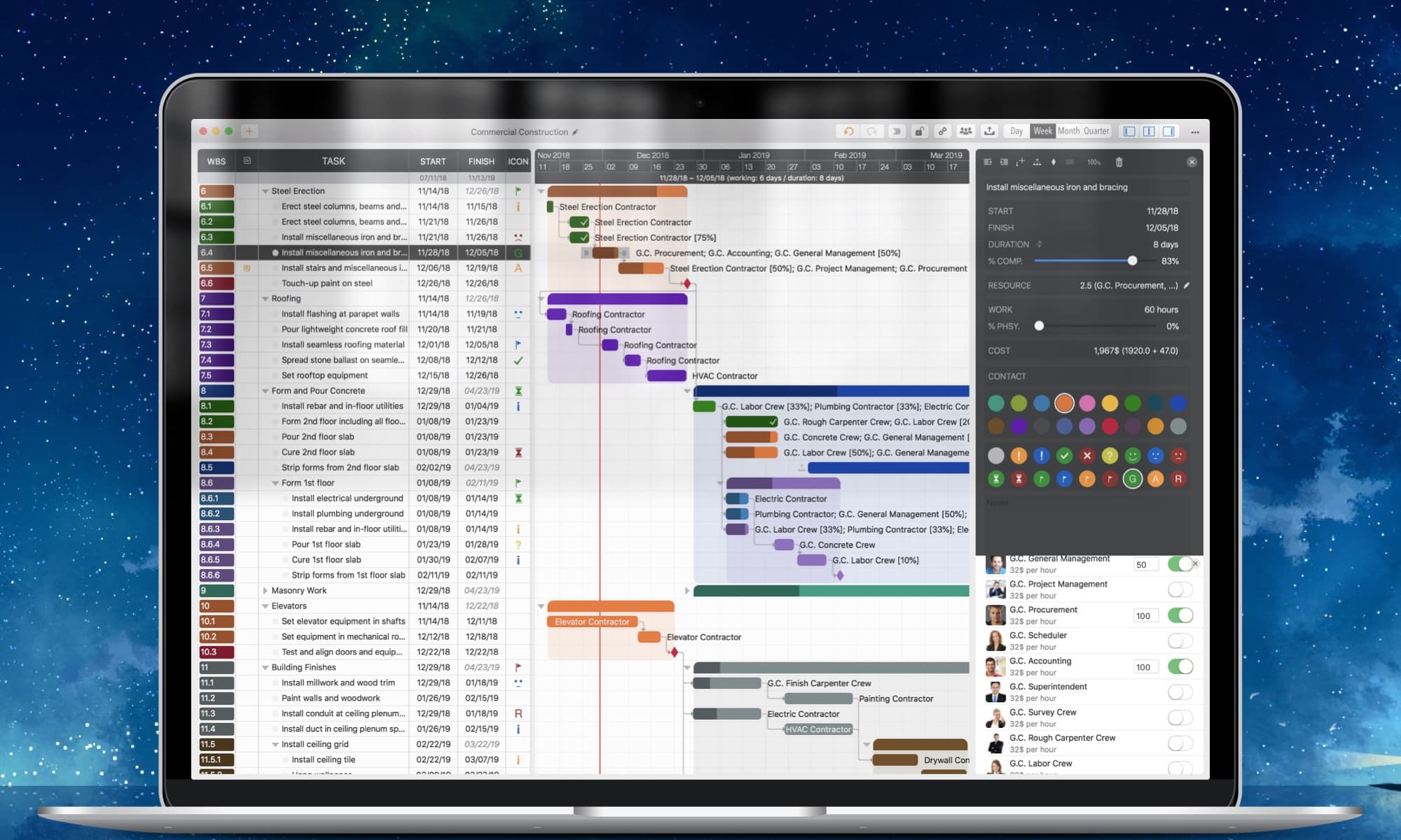
Simple, Intuitive, Efficient and Clean

QuickPlan brings the best features of Microsoft Project to iOS and macOS without the complexity—delivering the INTUITIVENESS and SIMPLICITY you know and love.


Export your projects to PDF, Excel, and image files with flexible and powerful customization options for content and layout.View Details
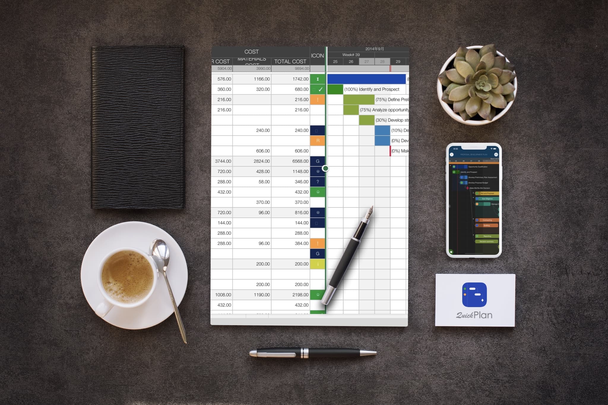
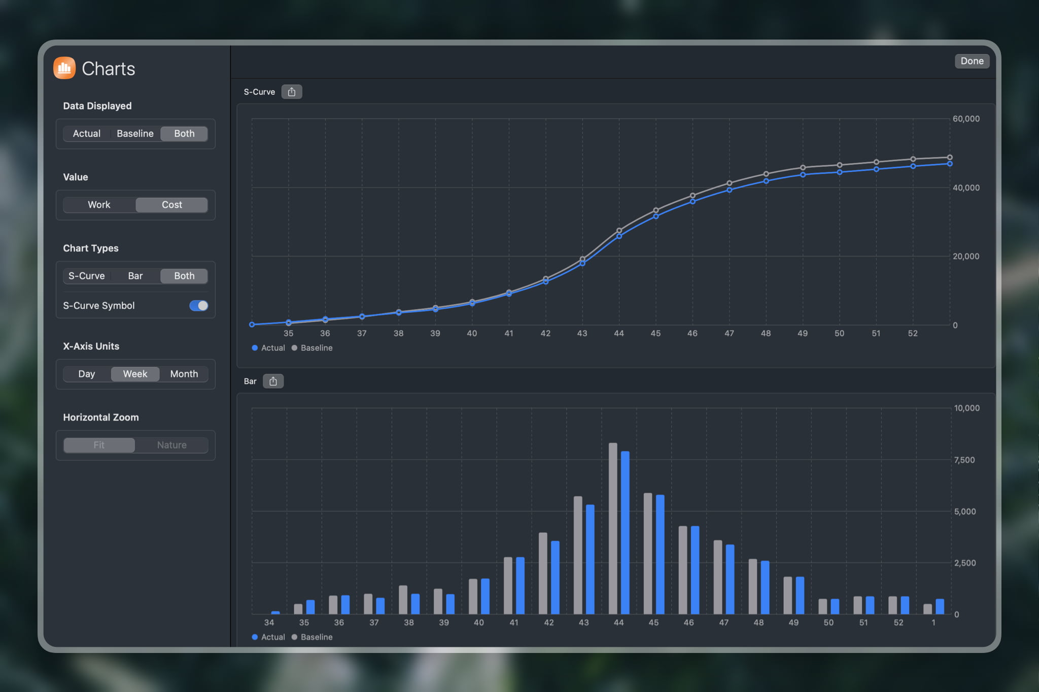
Create and compare baselines, generate reports, and customize S-Curve and Bar charts with ease.
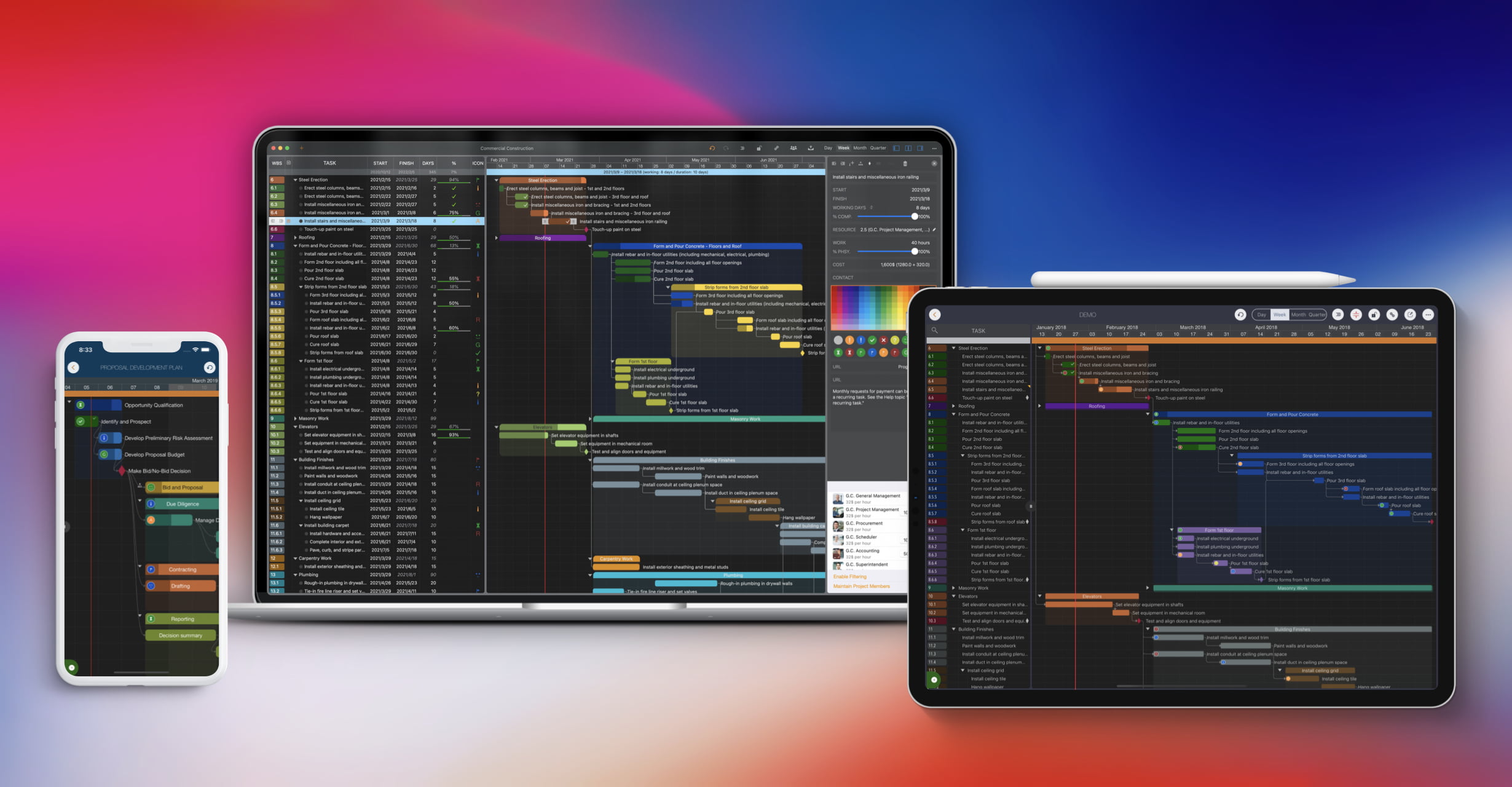
Share projects seamlessly across teams and devices using AirDrop, Dropbox, OneDrive, and other cloud storage services.

Sync project files between iOS and Mac devices via iCloud Drive.View Details

Export to Microsoft Project files (.XML format) and import from Microsoft Project files (.xml format).View Details

Import from Mind Map (.opml) files, and export to OPML format (QuickPlan for Mac).View Details

Simplify input/output in the project management process with Swift Apps WBS.View Details

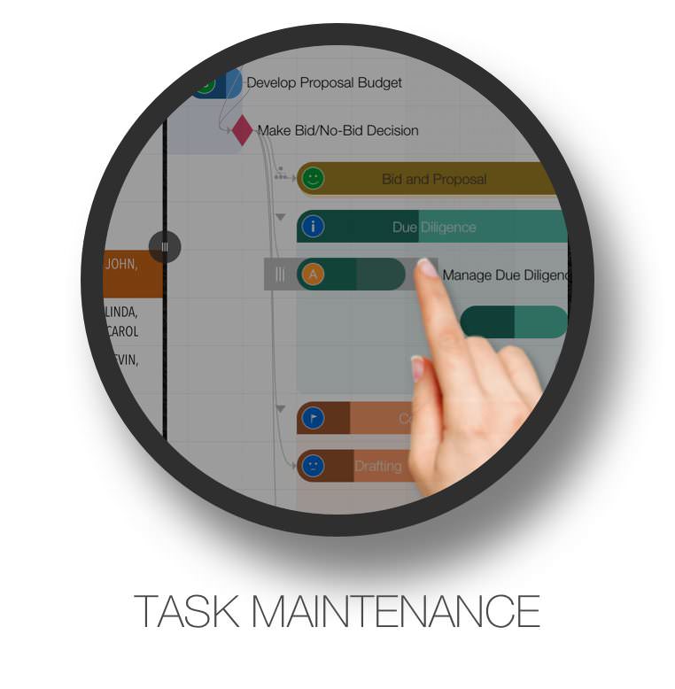
Today Widget, local notifications, and in-app Today list with multiple project selection options.View Details


Dob Chris
QuickPlan app is the best planning app I have ever used. It is very easy to use and helps me to be more efficient in my work. It has all the features I need to plan my projects effectively and collaborate with my team members smoothly. It is smart and strong enough to handle complex projects and large data sets. I highly recommend QuickPlan app to anyone who wants to plan smart and work easy. 👍
Txavatar
I have all the project geek merit badges – PMP certified, contributing author of the PMBoK, and a 20 year veteran of running projects up to thousands of personnel and billions of dollars. This tool shines in regard to easy of use combined with functionality. 99% of the users of Microsoft Project can’t properly use more than 10% of the application as everyone geeks out and wants more functions and more gadgets. QPP allows you to QUICKLY get a project sketched out and running. Earned Value Calculations and Resource Leveling? Yeah good luck with that on any tool. Im not going to suggest any more functionality to this tool to avoid unnecessarily complicating it but I will ask for a web-based or Mac-based app to easier support the initial keying and loading of all the project activities. That’s not a shortcoming of QPP but rather of iPads, which simply aren’t as good as a full size keyboard for data entry.Thanks for a terrific App!!
Scott, PMP
This is my go to app for project planning and tracking on iOS. I’m using it daily to plan and track projects and have found it to be the best project management app for iOS thus far. The ability to quickly enter information, move it around and organize it so that clients and stakeholders can understand it is priceless. In addition to project tracking, I’m using it for high level program management reporting to align management stakeholders to the overall plan and status.The developer has done a great job with the user interface and user experience. There are video tutorials available on how to use the app making it very clear on how to use. I’ve found it to be very intuitive which has made it easy to learn and use so I can quickly make changes while discussing the project with clients.The export functions are great making it easy to send a snapshot via PDF, Excel or PNG to stakeholders and resources to keep everyone on the same page with the project. Exporting XML works great when it’s time to make the schedule more complex than what should be managed on the iPad or if needed to align with an enterprise project reporting tool.I’m using the app daily and have found it to be the best project planning tool on iOS that is available.
Switch your multimeter ground lead to the (chassis ground or the negative leg of a secondary capacitor).
Check for burnt components, dry joints near transformers, and filter capacitors that may be bulging or leaking. 2. Signal Input/Input Conditioning Circuit
The execution layer of the schematic relies on high-efficiency switching.
Are you checking a (like the SMPS or IGBT)? Share public link
If , trace backward through the bridge rectifier to the fuse.
The power section of the CHK-V9.04G typically features a dual-rail topology.
or similar) are commonly used to isolate the sensitive control logic from high-voltage inputs. Protects the logic circuit from input surges. 3. Core Logic & Microcontroller Section
The CHK-V9.04G circuit diagram is a specific type of circuit diagram that represents a particular electronic circuit. The "CHK" prefix likely indicates that it's a checking or a verification circuit, while "V9.04G" suggests that it's a version 9.04G of the circuit. The diagram consists of various components, including resistors, capacitors, inductors, diodes, transistors, and integrated circuits.
: A clear and accurate circuit diagram is invaluable for anyone trying to repair or maintain the device. It provides a roadmap of how the device is constructed and how its various parts are interconnected.
Before diving into the diagram, we must understand the board's role. The CHK-V9.04G is generally a combined with a motor driver interface. Unlike a standard computer PSU, this board handles:
Filter out Electromagnetic Interference (EMI) and Radio Frequency Interference (RFI) to prevent noise from leaking back into your household grid. Bridge Rectification and Bulk Filtration (Hot Side)
Absorbs voltage spikes (e.g., lightning strikes).
High-value resistor divider networks (comprising 240kΩ to 470kΩ precision resistors) step down the AC input voltage and the IGBT collector voltage for MCU monitoring.
Before diving into the specifics of the CHK-V9.04G circuit diagram, it's essential to understand what a circuit diagram is. A circuit diagram, also known as a schematic diagram, is a visual representation of an electronic circuit. It uses standardized symbols and notations to illustrate the components, connections, and relationships between various parts of the circuit. Circuit diagrams are crucial for designing, building, and troubleshooting electronic circuits.
What is your device currently showing (e.g., completely dead, blinking LED, clicking noise)?
© 2013 ~ 2026 COPYRIGHT QUICKPLAN | All Rights Reserved
Swift Apps